Getting started with the Raspberry 4 GPIO (Raspberry Pi B+, 2, 3, Zero/W)
In this tutorial we will be having a look at how to use the GPIO on the Raspberry Pi 4. I will be explaining what the GPIO is, how to use it and the different types of pins available on the GPIO. Let’s get started!
What is the GPIO?
GPIO stands for General purpose input output. It allows the Raspberry Pi to interface with electronics which can be controlled programmatically (usually Python but C++ also works). GPIO pins have 2 states, on and off. A different way of saying if a pin is on or off is if the pin is high or low. Using Python code, we are able to control pins turning them off and on. A simple use case of using the GPIO could be making an LED blink using code. Check this out here!
If you are using the Raspberry Pi 4 or older models such as Raspberry Pi B+, 2 , 3, Zero/W they will have 40 pins. Some older models only have 26 pins. For the purpose of this tutorial, I will be focusing on the new models that have 40 pins.
GPIO pin layout
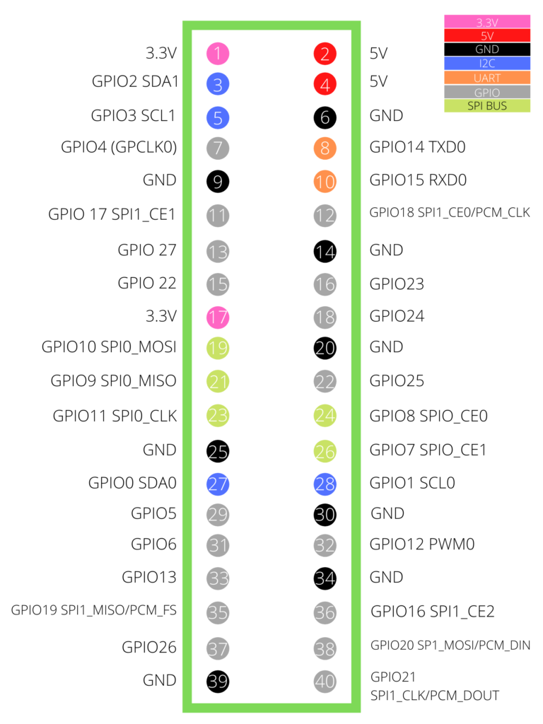
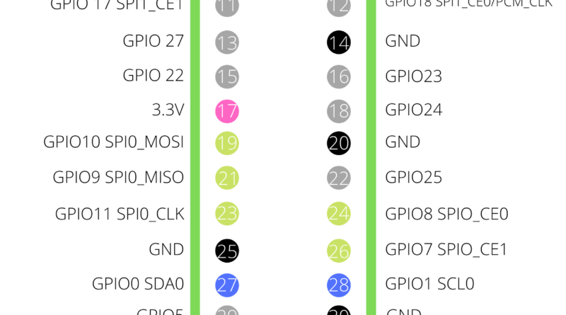
Above is a diagram depicting each GPIO pin on the Raspberry Pi. There are 8 different types of pins on the Raspberry Pi. Let’s go through each of them in detail. Note: some pins have more than one purpose. You will need to enable/disable certain interfaces to use them for your intended purpose.
3.3V (Pin 1, 17)
Outputs 3.3 V of power. Used for providing power to external electrical components.
5.5V (Pins 2,4)
Outputs 5V of power directly from the Raspberry Pi’s power input. Used for providing power to external electrical components.
GND (Pins 6, 9, 14, 20, 25, 30, 34, 39)
All ground pins on the Raspberry Pi are connected so it doesn’t matter which one you use. Generally speaking, the one closest to other connected wires is recommended to keep your wiring neat and tidy! Never connect a power pin directly to GND!
I2C (Pins 3, 5, 27, 28)
I2C (inter integrated circuit) is a protocol for low speed communication along two electrical lines. The Raspberry Pi has 2 I2C controllers. The two pins needed for I2C are Serial Clock Line (SCL) and Serial Data Line (SDA). To use I2C, you must enable it through raspi-config.
UART (Pins 8, 10)
UART (Universal Asynchronous Receiver Transmitter) is a protocol similar to I2C but without a clock. Timings are agreed in advance and start bits are added to each word to synchronize the sending and receiving of units.
General Purpose Pins (Pins 7, 11, 12, 13, 15, 16, 18, 22, 29, 31, 32, 33, 35, 36, 37, 38, 40)
General purpose pins can programmatically be set high or low and are used by electrical components, and usually controlled by using a library in Python or C++.
SPI (Pins 11, 12, 19, 21, 23, 24, 26, 35, 36, 38, 40)
SPI (Serial Peripheral Interface) is a protocol that transfers data between microcomputers and peripheral devices. It uses 4 lines (bus) to communicate with the target device. Multiple SPI devices can be connected to the same pins and controlled using the chip select pin. The Raspberry Pi 4 features 2 of these interfaces. SPI needs to be enabled in raspi-config before use.
PCM (Pins 12, 35, 38, 40)
PCM (Pulse code Modulation) is a method used to digitally represent sampled analog signals. To use PCM it must be enabled by modifying /boot/config.txt.
Want to get started using the GPIO? Checkout this tutorial on How to wire an LED to the GPIO (and make it blink!)